Long description: fig6
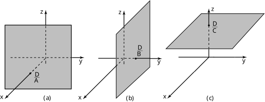
Alt text: Three diagrams illustrate the cross-sections of a rectangular solid in three different orientations on a three-dimensional coordinate system.
This description was generated by AI and has not been verified by a human. If you spot an error, please use the feedback link below.
- The first diagram, labeled (a), shows a square cross-section in the \(x\)-\(z\) plane, with the height labeled as \(D\) and the width labeled as \(A\). The origin is marked, and the axes \(x\), \(y\), and \(z\) are visible.
- The second diagram, labeled (b), shows a rectangular cross-section in the \(y\)-\(z\) plane, with the height labeled as \(D\) and the width labeled as \(B\). The origin is marked, and the axes \(x\), \(y\), and \(z\) are visible.
- The third diagram, labeled (c), shows a diagonal cross-section in a plane tilted relative to the axes, with the height labeled as \(D\) and the width labeled as \(C\). The origin is marked, and the axes \(x\), \(y\), and \(z\) are visible.