Long description: Figextra1
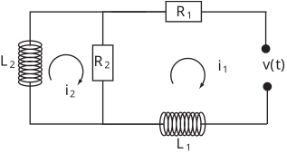
Alt text: A circuit diagram showing three components, two inductors labeled \(L_1\) and \(L_2\), and one resistor labeled \(R_2\), connected with nodes for voltage \(v(t)\) and currents \(i_1\) and \(i_2\).
This description was generated by AI and has not been verified by a human. If you spot an error, please use the feedback link below.
- The circuit diagram depicts a series connection involving three components: an inductor \(L_2\), a resistor \(R_2\), and another inductor \(L_1\).
- There are electrical nodes indicated in the diagram; one node is labeled with the voltage \(v(t)\) and is connected to the right side of the circuit elements.
- The current flowing through \(L_2\) is labeled \(i_2\), indicated by a clockwise arrow around \(L_2\) and \(R_2\) when viewed from the top.
- The current flowing through the branch containing \(R_2\) and \(L_1\) is labeled \(i_1\), indicated by a clockwise arrow within that branch.