Long description: LRCcircuit
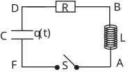
Alt text: A circuit diagram showing a capacitor, resistor, inductor, and a switch connected in series.
This description was generated by AI and has not been verified by a human. If you spot an error, please use the feedback link below.
- The circuit diagram illustrates a series RLC circuit connected between two nodes labeled D and F on the left, and nodes B and A on the right.
- On the left side, a capacitor is drawn, labeled with a charge \(q(t)\) across it, connecting node D to node F.
- In series with the capacitor, a resistor labeled \(R\) is placed between node D and the right side of the circuit.
- On the right side, an inductor, represented by a coil, is connected between node B and node A.
- A switch, labeled \(S\), is placed in the lower portion of the circuit, connecting node F to node A, allowing for an open or closed circuit path.