Long description: fig4
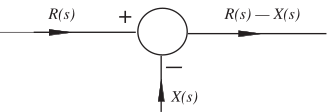
Alt text: A block diagram showing a summing junction where the input signals \(R(s)\) and \(X(s)\) are combined to produce an output signal \(R(s) - X(s)\).
This description was generated by AI and has not been verified by a human. If you spot an error, please use the feedback link below.
- The diagram features a summing junction, represented by a circle with a plus sign inside, indicating addition.
- An input signal labeled \(R(s)\) enters the junction from the top left.
- A second input signal labeled \(X(s)\) enters the junction from the bottom.
- The output signal, labeled \(R(s) - X(s)\), exits the junction towards the right.