Long description: fig5
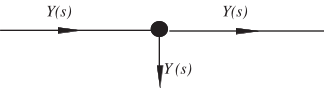
Alt text: A diagram shows an input signal, \(Y(s)\), entering a node and a second output signal, \(Y(s)\), exiting the same node, suggesting a connection or parallel path.
This description was generated by AI and has not been verified by a human. If you spot an error, please use the feedback link below.
- The image displays a schematic diagram with two horizontal lines representing signals in the Laplace domain, denoted as \(Y(s)\).
- An input signal, labeled \(Y(s)\), approaches a central node from the left.
- A vertical line descends from the central node, representing a signal path also labeled \(Y(s)\).
- The horizontal line continues to the right from the central node, carrying an output signal also labeled \(Y(s)\).
- This arrangement depicts a single point node with three associated signal paths, all labeled \(Y(s)\).