Long description: fig9
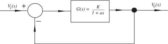
Alt text: A block diagram showing an input signal, \(V_1(s)\), being subtracted from a signal that is then passed through a block with the transfer function \(G(s) = \frac{K}{1+as}\) to produce an output signal, \(V_0(s)\).
This description was generated by AI and has not been verified by a human. If you spot an error, please use the feedback link below.
- The diagram illustrates a standard feedback control block diagram setup.
- An input signal, denoted as \(V_1(s)\), enters the diagram at a summing junction.
- A second signal, which is the output signal \(V_0(s)\), is fed back to the summing junction with a negative sign, indicating a subtraction operation.
- The output of the summing junction feeds into a block whose transfer function is given by \(G(s) = \frac{K}{1+as}\).
- The output of this block is labeled \(V_0(s)\).