Long description: SeriespDesign
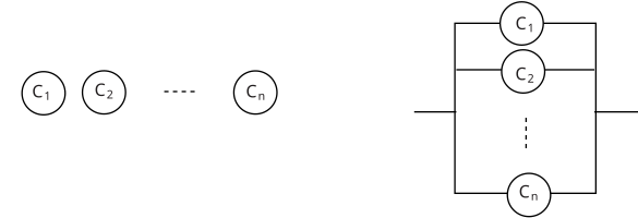
Alt text: A circuit diagram showing capacitors connected in parallel.
This description was generated by AI and has not been verified by a human. If you spot an error, please use the feedback link below.
- The diagram depicts a circuit setup with multiple capacitors, labeled from \(C_1\) to \(C_n\).
- These capacitors are arranged vertically, connected across two common horizontal lines representing the voltage source or circuit terminals.
- The capacitor \(C_1\) is the topmost component, followed by \(C_2\), and then a series of dashed lines indicating subsequent capacitors down to \(C_n\), which is the bottommost component.
- This parallel arrangement signifies that the capacitors are connected such that the voltage across each capacitor is the same.